01 / BLIND ZONE
No clear stopping reference
The pallet blocks the driver's direct view of the exit, increasing the chance of a rear-edge over-run.
Stop Line is a progressive, two-stage loading safety system being developed to reduce rear-threshold over-runs, injuries and damage to goods and equipment. Full-width amber and red markers guide drivers moving pallets and roll cages towards the rear of a vehicle—even when the load hides the edge.
Amber Warns Red Stops
The pallet blocks the driver's direct view of the exit, increasing the chance of a rear-edge over-run.
One misjudgement can injure the operator, damage the load or equipment, and expose nearby road users.
Amber signals the final approach. Red marks the stopping boundary, with both lines still visible at the pallet's sides.
As the driver pushes a pallet towards the tail-lift, the load crosses the amber line first. This signals entry into the final approach zone. The driver then stops the pallet before the red exit threshold.
Visible around the pallet. Because each line runs across the full vehicle width, it remains visible on either side of a standard UK pallet. The driver can look around the load and use those side markers instead of guessing the hidden distance to the rear edge.
Crossing amber signals entry into the final approach zone. Reduce speed and prepare to stop.
Stop the pallet or roll cage before red. This is the final boundary before the tail-lift.
Line spacing and distance from the rear edge are confirmed for each vehicle and loading method.
The illustration shows the sequence only; it is not a stopping-distance rating.
TfL-funded research found that safer vehicle design begins by making critical hazards directly visible. Stop Line applies that principle to rear loading: when a pallet or roll cage obscures the exit edge, full-width floor markers restore a clear approach and stopping reference.
Using collision-derived pedestrian and cyclist scenarios, the researchers compared how cab geometry, window design and driver position changed the size of direct-vision blind spots.
STOP LINE RELEVANCE Vehicle layouts differ, so the rear boundary and amber approach position should be confirmed for each body and loading method.
TfL/LDS report · Executive Summary, p.4STOP LINE RELEVANCE When a critical reference is hidden by physical geometry, the risk should be addressed through design as well as operator training.
TfL/LDS report · Key Findings 6.4.1, p.380Cab height, window design and driver position changed how much of a nearby pedestrian or cyclist could be seen directly.
Keep the reference visible at the point of action.
Full-width floor cues remain visible beside a pallet or roll cage, replacing a hidden edge with a progressive stopping decision.
The report linked blind-spot size to cab height, window-aperture design and the driver's position. Low-entry cabs demonstrated substantial direct-vision benefits over standard layouts.
The researchers questioned whether small, distorted fragments of a road user can always be recognised across six mirrors in high-workload situations, and concluded that direct vision should be prioritised in vehicle design.
Inside the body, a pallet or roll cage can hide the rear edge from the person moving it. Training cannot restore a reference that has physically disappeared behind the load.
Stop Line proposes a direct, full-width cue that remains visible at the load's sides: amber signals the final approach and red defines the rear stopping boundary.
The Research Bridge. Rear-threshold design deserves the same disciplined attention: trials must assess operator safety, exposure to people nearby, and damage or disruption to the operation.
Evidence boundary. The TfL-funded report studied cab visibility around HGVs; it did not evaluate rear loading, Stop Line or economic outcomes. The rear-threshold connection above is Stop Line's design inference and proposed trial case—not a TfL finding, requirement or endorsement. TfL logos are not displayed because prior written permission is required for third-party use.
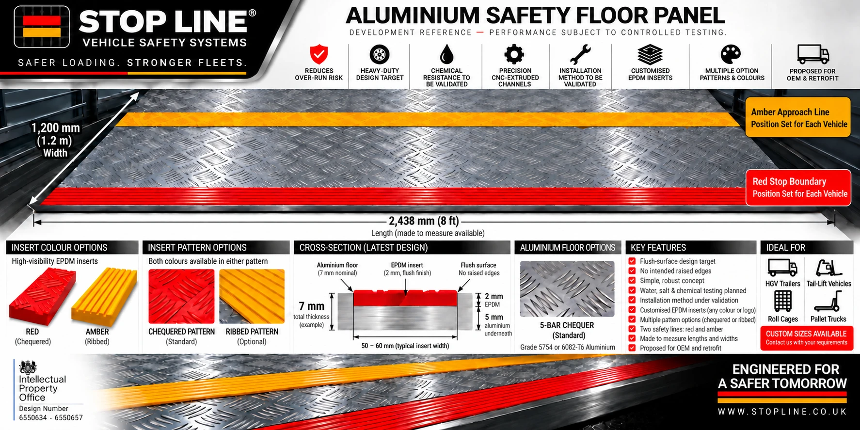
Specify the made-to-measure five-bar aluminium safety floor, then select the amber ribbed, red chequered or original bespoke EPDM insert route required for the application.
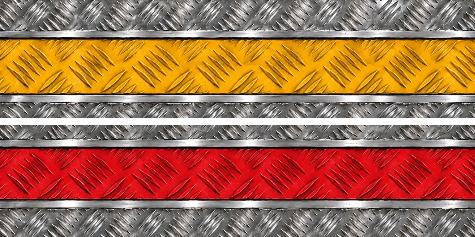 EPDM Inserts
A replaceable insert platform for safety visibility and vehicle-specific performance. Choose the amber approach insert, red stopping insert or commission an original made-to-order EPDM specification matched to the installed Stop Line channel.
One engineered profile, three commercial routes. Amber approach, red stop and a fully original bespoke specification—available for new Stop Line floors and matched replacement programmes, subject to final manufacturing validation. During routine cleaning or insert servicing, the EPDM and its seating area must be wiped clean and dry to limit trapped moisture, residue, mould and mildew.
VEHICLE-SPECIFIC SAFETY SYSTEMStop Line® builds two unmistakable full-width decisions into a made-to-measure five-bar aluminium floor. Amber marks the final approach; red defines the rear stopping boundary. The reference build uses a 7 mm nominal aluminium floor with replaceable EPDM inserts approximately 2 mm deep and 50–60 mm wide, seated flush in machined channels. Routine operator care keeps each insert and its seating area clean, dry and ready for inspection.
Every material, dimension and line position is being developed around the vehicle, the load and the people who operate it—not a one-size-fits-all assumption.
Nominal aluminium reference build; final gauge remains vehicle-specific.
Typical insert width shown in the current hero reference design.
Wet anti-slip development target for independent testing.
Test planning references BS EN 1756-1:2021 for tail-lift safety context, BS EN 16165:2021 for slip-resistance evaluation and ISO 1817:2026 as the proposed reference for evaluating the effect of liquids on EPDM rubber; the test laboratory must confirm the final method, exposure conditions and acceptance criteria. Stop Line is not yet presented as certified to these standards.
Before installation, record the vehicle, load, loading task and existing controls. Test prototype geometry, materials, durability and operator response against that baseline, including installation and replacement time.
Define the vehicle, loading task, existing controls and events to be compared.
Introduce the prototype and collect consistent evidence in normal fleet use.
Compare the result, identify limitations and decide whether to refine, extend or stop.
Record when operators begin slowing, where loads stop and every red-line over-run or recovery.
Log tip, drift, rollback and emergency-catch events by load type, weight and direction of travel.
Compare movement time, pauses and operator corrections before and after the Stop Line installation.
Inspect wet and dry traction, insert wear, retention, flushness and chequer-plate condition at agreed intervals.
Check amber and red visibility under low light, dirt, moisture, pallet obstruction and routine cleaning.
Capture structured feedback on clarity, stopping confidence, usability and otherwise unreported events.
Record briefing time, first-use understanding, repeated errors and whether the two-stage warning becomes intuitive in routine work.
Measure vehicle downtime, installation duration and the time required to remove and renew a worn insert without replacing the floor.
We are seeking selected operators, pallet networks, bodybuilders and safety partners for controlled prototype trials.
Ideal for one depot, one vehicle type and one clearly defined loading operation.
Built From the Cab. Engineered for the Fleet.
Stop Line comes from more than 15 years of professional HGV driving and first-hand understanding of how a small loading error can become a costly, dangerous incident in seconds.
The idea is deliberately simple: give the person moving the load a better visual decision point, then engineer that intervention to withstand the reality of commercial fleet work.
The registered design portfolio supports Stop Line's commercialisation, licensing and integration strategy. Product performance remains subject to controlled testing and documentary verification.

UK Intellectual Property Office design portfolio: 6550634–6550657

Reference pending. No EUIPO registration or endorsement is claimed until confirmed filing details are available.

Registered in the United Kingdom with Companies House: 17416504View Official Record
Protected design, evidence-led product. UK registrations document the registered visual representations of the Stop Line portfolio. Their legal scope is determined by the registrations and applicable law; they do not replace engineering validation, certification or proof of operational performance.
Test reports, applicable standard references and material data will be listed here once the supporting documents have been obtained and verified. No product certification is claimed at this stage.
DOCUMENTATION PENDING